Bicubic or Bezier patches are useful surface representations because they allow an easy definition of surfaces using only a few control points. The control points serve to determine the shape of the patch. Instead of defining the vertices of triangles, we simply give the coordinates of the control points. A single patch has 16 control points, one at each corner, and the rest positioned to divide the patch into smaller sections. For ray-tracing (or rendering) the patches are approximated using triangles.
Bezier patches are almost always created using a third party modeler so for this tutorial, we will use moray (any other modeler that supports Bezier patches and POV-Ray can also be used). We will use moray only to create the patch itself, not the other elements of the scene.
Note that moray is not included with POV-Ray. It is a separate shareware program that currently only runs on MS-Dos and Win95/NT but this tutorial assumes you are using the MS-Dos version. If you do not have moray or are not on MS-Dos, you can still render the sample scene described below, even though you cannot see how moray created it. Simply type in the bicubic_patch declaration listed below.
Bezier patches are actually very useful and, with a little practice, some pretty amazing things can be created with them. For our first tutorial, let's make a sort of a teepee/tent shape using a single sheet patch.
First, we start moray and, from the main edit screen, we click on "CREATE". We Name our object Teepee. The "CREATE BEZIER PATCH" dialogue box will appear. We have to make sure that "SHEET" is depressed. We click on "OK, CREATE". At the bottom of the main edit screen, we click on "EXTENDED EDIT".
We hold the cursor over the "TOP" view and right click to make the pop-up menu appear. We click on "MAXIMIZE". We [ALT]-drag to zoom in a little. We click on "MARK ALL", and under the transformation mode box, "UFRM SCL". We drag the mouse to scale the patch until it is approximately four units wide. We click on "TRANSLATE", and move the patch so that its center is over the origin. We right click "MINIMIZE" and "UNMARK ALL".
We [SHIFT]-drag a box around the lower right control point to mark it. We [ALT]-zoom into the "FRONT" view so that we can see the patch better. In the "FRONT" view, we "TRANSLATE" that point 10 units along the negative z-axis (we note that in MORAY z is up). We "UNMARK ALL". We repeat this procedure for each of the other three corner points. We make sure we remember to "UNMARK ALL" once each point has been translated. We should have a shape that looks as though it is standing on four pointed legs. We "UNMARK ALL".
Working once again in the "TOP" view, we [SHIFT]-drag a box around the four center control points to mark them. We right-click over the "TOP" view and "MAXIMIZE". We click on "UFRM SCL" and drag the mouse to scale the four points close together. We [ALT]-drag to zoom closer and get them as close together as we can. We [ALT]-drag to zoom out, right click and "MINIMIZE".
In the "FRONT" view, we "TRANSLATE" the marked points 10 units along the positive z-axis. We "UNMARK ALL". The resulting shape is quite interesting, was simple to model, and could not be produced using CSG primitives. Now let's use it in a scene.
We click on "DONE" to return to the main edit screen. We note that u_steps and v_steps are both set to 3 and flatness is set to 0.01. We leave them alone for now. We click on "FILES" and then "SAVE SEL" (save selection). We name our new file teepee1.mdl. We press [F3] and open teepee1.mdl. There is no need to save the original file. When teepee1 is open, we create a quick "dummy" texture (moray will not allow us to export data without a texture). We use white with default finish and name it TeePeeTex. We apply it to the object, save the file and press [CTRL-F9]. moray will create two files: teepee1.inc and teepee1.pov.
We exit moray and copy teepee1.inc and teepee1.pov into our working directory where we are doing these tutorials. We create a new file called bezdemo.pov and edit it as follows:
  #include "colors.inc"

  camera {

    location <0, .1, -60>

    look_at 0

    angle 40

  }

  background { color Gray25 }  //to make the patch easier to see

  light_source { <300, 300, -700> White }

  plane { y, -12

    texture {

      pigment {

        checker

        color Green

        color Yellow

      }

    }

  }
Using a text editor, we create and declare a simple texture for our teepee object:
  #declare TeePeeTex = texture {

    pigment {

      color rgb <1, 1, 1,>

    }

    finish {

      ambient .2

      diffuse .6

    }

  }
We paste in the bezier patch data from teepee1.pov (the additional object keywords added by moray were removed):
  bicubic_patch {

    type 1 flatness 0.0100 u_steps 3 v_steps 3,

    <-5.174134, 5.528420, -13.211995>,

    <-1.769023, 5.528420, 0.000000>,

    <1.636088, 5.528420, 0.000000>,

    <5.041199, 5.528420, -13.003932>,

    <-5.174134, 1.862827, 0.000000>,

    <0.038471, 0.031270, 18.101474>,

    <0.036657, 0.031270, 18.101474>,

    <5.041199, 1.862827, 0.000000>,

    <-5.174134, -1.802766, 0.000000>,

    <0.038471, 0.028792, 18.101474>,

    <0.036657, 0.028792, 18.101474>,

    <5.041199, -1.802766, 0.000000>,

    <-5.174134, -5.468359, -13.070366>,

    <-1.769023, -5.468359, 0.000000>,

    <1.636088, -5.468359, 0.000000>,

    <4.974128, -5.468359, -12.801446>

    texture {

      TeePeeTex

    }

    rotate -90*x  // to orient the object to LHC

    rotate 25*y   // to see the four "legs" better

  }
We add the above rotations so that the patch is oriented to POV-Ray's left-handed coordinate system (remember the patch was made in moray in a right handed coordinate system), so we can see all four legs. Rendering this at 200x150 -a we see pretty much what we expect, a white teepee over a green and yellow checkered plane. Let's take a little closer look. We render it again, this time at 320x200.
Now we see that something is amiss. There appears to be sharp angling, almost like facing, especially near the top. This is indeed a kind of facing and is due to the u_steps and v_steps parameters. Let's change these from 3 to 4 and see what happens.
That's much better, but it took a little longer to render. This is an unavoidable tradeoff. If we want even finer detail, we must use a u_steps and v_steps value of 5 and set flatness to 0. But we must expect to use lots of memory and an even longer tracing time.
Well, we can't just leave this scene without adding a few items just for interest. We declare the patch object and scatter a few of them around the scene:
  #declare TeePee = bicubic_patch {

    type 1 flatness 0.0100 u_steps 3 v_steps 3,

    <-5.174134, 5.528420, -13.211995>,

    <-1.769023, 5.528420, 0.000000>,

    <1.636088, 5.528420, 0.000000>,

    <5.041199, 5.528420, -13.003932>,

    <-5.174134, 1.862827, 0.000000>,

    <0.038471, 0.031270, 18.101474>,

    <0.036657, 0.031270, 18.101474>,

    <5.041199, 1.862827, 0.000000>,

    <-5.174134, -1.802766, 0.000000>,

    <0.038471, 0.028792, 18.101474>,

    <0.036657, 0.028792, 18.101474>,

    <5.041199, -1.802766, 0.000000>,

    <-5.174134, -5.468359, -13.070366>,

    <-1.769023, -5.468359, 0.000000>,

    <1.636088, -5.468359, 0.000000>,

    <4.974128, -5.468359, -12.801446>

    texture {

      TeePeeTex

     }

     rotate -90*x // to orient the object to LHC

     rotate 25*y  // to see the four "legs" better

  }

  object { TeePee }

  object { TeePee translate <8, 0, 8> }

  object { TeePee translate <-9, 0, 9> }

  object { TeePee translate <18, 0, 24> }

  object { TeePee translate <-18, 0, 24> }
That looks good. Let's do something about that boring gray background. We delete the background declaration and replace it with:
  plane { y, 500

    texture {

      pigment { SkyBlue }

      finish { ambient 1 diffuse 0}

     }

     texture {

       pigment {

         bozo

         turbulence .5

         color_map {

           [0 White]

           [1 White filter 1]

         }

       }

       finish { ambient 1 diffuse 0 }

       scale <1000, 250, 250>

       rotate <5, 45, 0>

    }

  }
This adds a pleasing cirrus-cloud filled sky. Now, let's change the checkered plane to rippled sand dunes:
  plane {y,-12

    texture {

      pigment {

        color <.85, .5, .15>

      }

      finish {

        ambient .25

        diffuse .6

        crand .5

      }

      normal {

        ripples .35

        turbulence .25

        frequency 5

      }

      scale 10

      translate 50*x

    }

  }
We render this. Not bad! Let's just add one more element. Let's place a golden egg under each of the teepees. And since this is a bezier patch tutorial, let's make the eggs out of bezier patches.
We return to moray and create another bezier patch. We name it Egg1 and select "CYLINDRICAL 2 - PATCH" from the "CREATE BEZIER PATCH" dialogue box. We click on "EXTENDED EDIT". We "MARK ALL" and rotate the patch so that the cylinder lays on its side. We "UNMARK ALL". In the "FRONT" view, we [SHIFT]-drag a box around the four points on the right end to mark them. In the "SIDE" view, we right click and "MAXIMIZE". We [ALT]-drag to zoom in a little closer. We "UFRM SCL" the points together as close as possible. We zoom in closer to get them nice and tight. We zoom out, right click and "MINIMIZE".
We click on "TRANSLATE" and drag the points to the left so that they are aligned on the z-axis with the next group of four points. This should create a blunt end to the patch. We repeat this procedure for the other end. We "UNMARK ALL".
In the "FRONT" view, the control grid should be a rectangle now and the patch should be an ellipsoid. We [SHIFT]-drag a box around the upper right corner of the control grid to mark those points. We then [SHIFT]-drag a box around the lower right corner to mark those points as well. In the "SIDE" view, we "UFRM SCL" the points apart a little to make that end of the egg a little wider than the other. We "UNMARK ALL".
The egg may need a little proportional adjustment. We should be able to "MARK ALL" and "LOCAL SCL" in the three views until we get it to look like an egg. When we are satisfied that it does, we "UNMARK ALL" and click on done. Learning from our teepee object, we now go ahead and change u_steps and v_steps to 4.
We create a dummy texture, white with default finish, name it EggTex and apply it to the egg. From the FILES menu, we "SAVE SEL" to filename egg1.mdl. We load this file and export ([CTRL F9]). We exit moray and copy the files egg1.inc and egg1.pov into our working directory.
Back in bezdemo.pov, we create a nice, shiny gold texture:
  #declare EggTex = texture {

    pigment { BrightGold }

    finish {

      ambient .1

      diffuse .4

      specular 1

      roughness 0.001

      reflection .5

      metallic

    }

  }
And while we're at it, let's dandy up our TeePeeTex texture:
  #declare TeePeeTex = texture {

    pigment { Silver }

    finish {

      ambient .1

      diffuse .4

      specular 1

      roughness 0.001

      reflection .5

      metallic

    }

  }
Now we paste in our egg patch data and declare our egg:
  #declare Egg = union { // Egg1

    bicubic_patch {

      type 1 flatness 0.0100 u_steps 4 v_steps 4,

      <2.023314, 0.000000, 4.355987>,

      <2.023314, -0.000726, 4.355987>,

      <2.023312, -0.000726, 4.356867>,

      <2.023312, 0.000000, 4.356867>,

      <2.032037, 0.000000, 2.734598>,

      <2.032037, -1.758562, 2.734598>,

      <2.027431, -1.758562, 6.141971>,

      <2.027431, 0.000000, 6.141971>,

      <-1.045672, 0.000000, 3.281572>,

      <-1.045672, -1.758562, 3.281572>,

      <-1.050279, -1.758562, 5.414183>,

      <-1.050279, 0.000000, 5.414183>,

      <-1.044333, 0.000000, 4.341816>,

      <-1.044333, -0.002947, 4.341816>,

      <-1.044341, -0.002947, 4.345389>,

      <-1.044341, 0.000000, 4.345389>

    }

    bicubic_patch {

      type 1 flatness 0.0100 u_steps 4 v_steps 4,

      <2.023312, 0.000000, 4.356867>,

      <2.023312, 0.000726, 4.356867>,

      <2.023314, 0.000726, 4.355987>,

      <2.023314, 0.000000, 4.355987>,

      <2.027431, 0.000000, 6.141971>,

      <2.027431, 1.758562, 6.141971>,

      <2.032037, 1.758562, 2.734598>,

      <2.032037, 0.000000, 2.734598>,

      <-1.050279, 0.000000, 5.414183>,

      <-1.050279, 1.758562, 5.414183>,

      <-1.045672, 1.758562, 3.281572>,

      <-1.045672, 0.000000, 3.281572>,

      <-1.044341, 0.000000, 4.345389>,

      <-1.044341, 0.002947, 4.345389>,

      <-1.044333, 0.002947, 4.341816>,

      <-1.044333, 0.000000, 4.341816>

    }

    texture { EggTex }

    translate <0.5, 0, -5>  // centers the egg around the origin

    translate -9.8*y        // places the egg on the ground

  }
We now place a copy of the egg under each teepee. This should require only the x- and z-coordinates of each teepee to be changed:
  object { Egg }

  object { Egg translate <8, 0, 8> }

  object { Egg translate <-9, 0, 9> }

  object { Egg translate <18, 0, 24> }

  object { Egg translate <-18, 0, 24> }
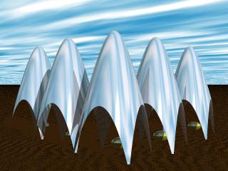
Scene build with different Bezier patches.
We render this at low resolution such as 320x240. Everything looks good so we run it again at 640x480. Now we see that there is still some facing near the top of the teepees and on the eggs as well. The only solution is to raise u_steps and v_steps from 4 to 5 and set flatness to 0 for all our bezier objects. We make the changes and render it again at 640x480. The facets are gone.